Diamond Specialist Certification Course
How to Measure an “Over The Limit” Refractive Index
Using a Micrometric Scale and Microscope to Measure OTL Refractive Indices
Adding a micrometric scale to your microscope can be a great help. F.S.H. Tisdall and B.W. Anderson (BSc, FGA, FKC) used this technique to measure RIs over 1.81 (without limits). However, its principal application is for either singly refractive gems or uniaxial doubly refractive gems. For the former, under good conditions and if the gem isn't too small, you can obtain an RI with better than 0.02 accuracy. You can also use this technique for determining the depth of an inclusion.
In the 1980s, gemologists utilized this technique by applying a small ruler and a vernier scale to a microscope. Nowadays, we can use digital calipers. Instead of taking measurements down to 0.1 mm (0.004 inch) with the vernier, you can reach 0.01 mm (0.0004 inch) with accuracy even better than ±0.02. You also have the advantage of zeroing the caliper in any position.
How to Upgrade Your Microscope
Let's apply these concepts. For this upgrade, you'll need the following:
- A digital caliper
- Two screws
- A few bolts
- An L-shaped piece of metal
Remember, this is only a guideline. Since each microscope has its own shape, dimensions, etc, some parts could interfere with the displacement of the digital reader or its position.
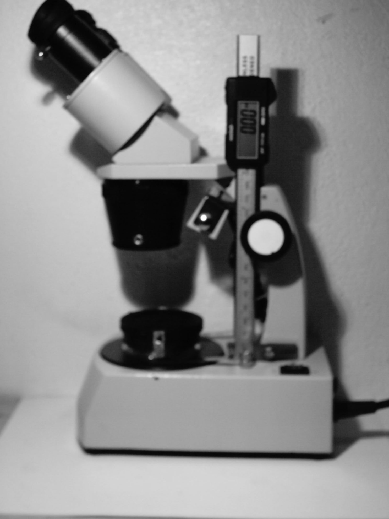
For this upgrade, you'll probably spend about $20. (You don't need an expensive caliper). Figure 1 above shows what this adaptation will typically look like.
Positioning the Caliper
Before you begin, carefully study how you'll attach your caliper to your microscope. Keep in mind that you want the caliper to move with the displacement of the objectives when focusing. Consider several different plans. Don't attempt the first idea you have. Be sure your adaptation will keep your caliper absolutely vertical and horizontal in relation to the planes of the microscope.
In my case, I did two trials before getting it right. You'll likely find that the best way to work with the caliper is to place it in an upside-down position. This will give you negative numbers. However, this is irrelevant, since you'll take them as positive values.
Caliper Cutting Advice
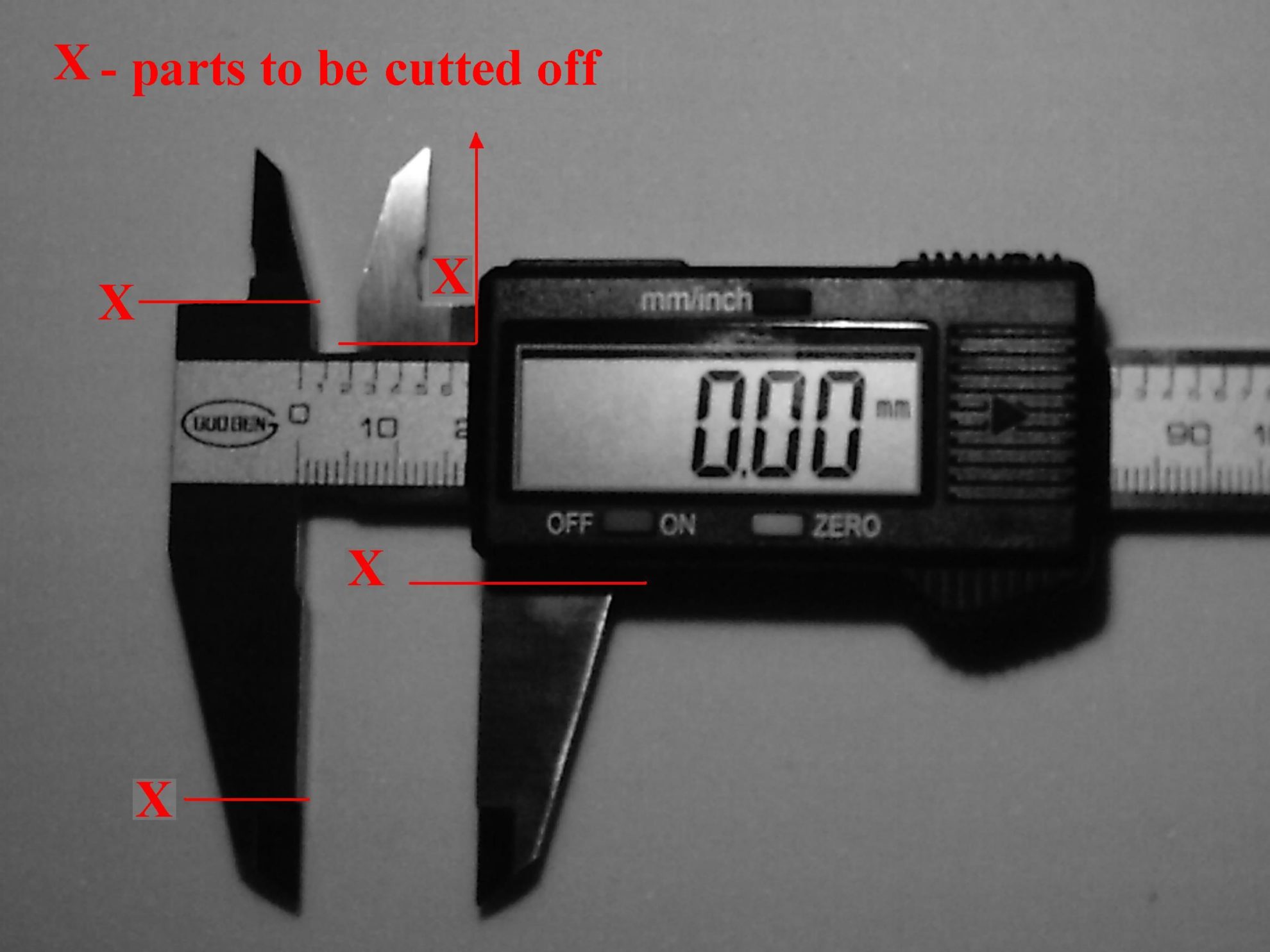
After the assembly, you must cut off some parts of the caliper. (Figure 2 shows the parts I had to cut). If you have a mini-drill with cutting discs, use it. If you don't have your own drill, have a metalwork shop cut the parts for you
Never cut the metal parts of your caliper without removing the reader first. The heat necessary for cutting the metal will ruin the reader's electronics.
Be careful when you disassemble your caliper. Do it step-by-step and make sure you understand where each piece belongs. For example, every caliper has a small, curved copper strip inside. It serves as a tension strip and is connected to a retention pin.
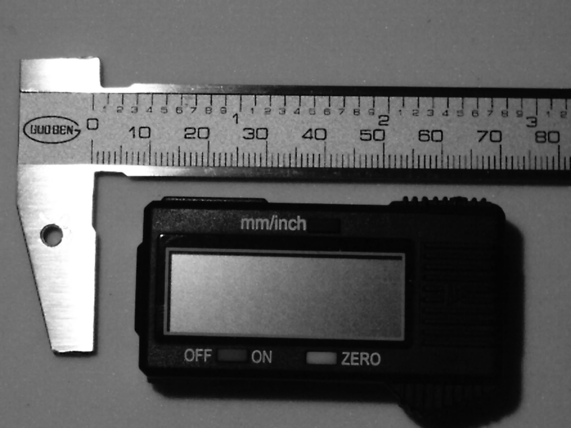
You can see the final result in Figure 3. Note the hole I made in the outer large jaw. It's about 3.5 mm (0.138 inch) and will serve as passage for a 3 mm (0.118 inch) screw.
Aligning the Horizontal and Vertical Axes
The top of the caliper remains untouched because it will serve to perfectly align the horizontal and vertical axes. See Figure 4.
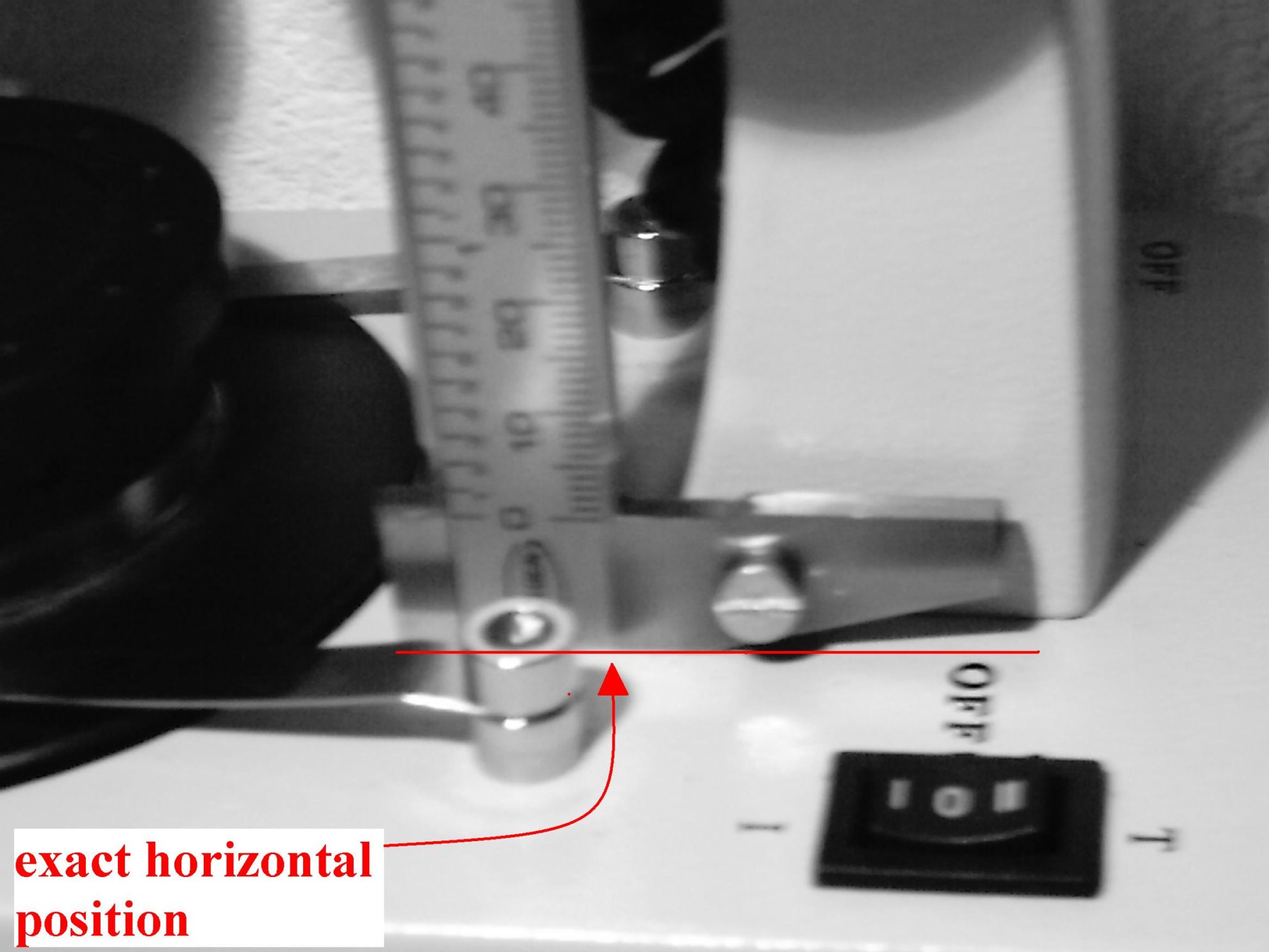
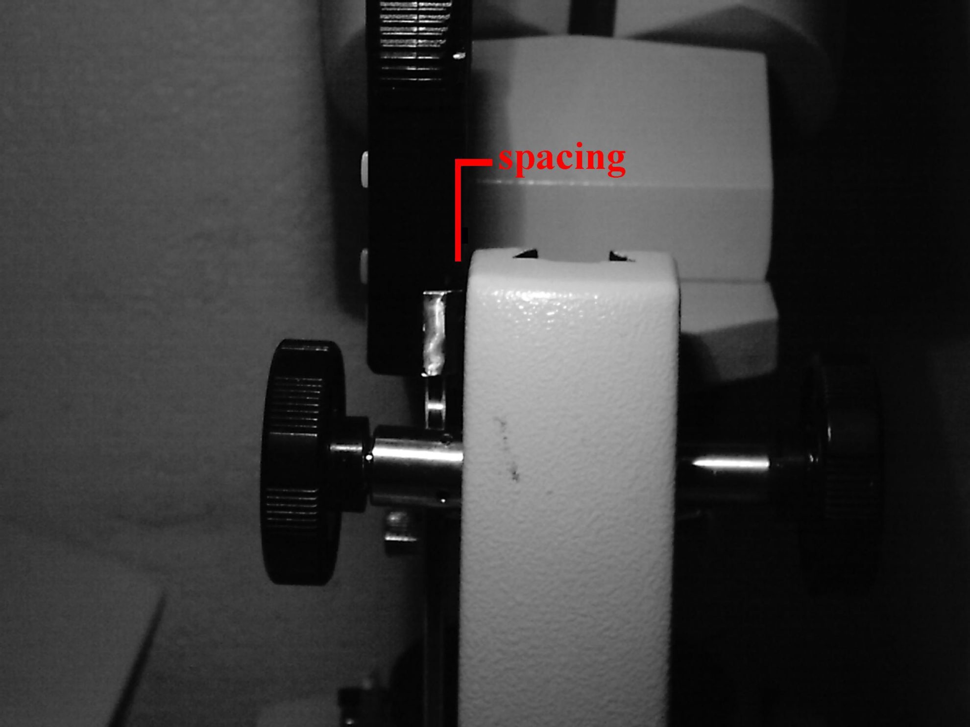
Of course, after careful positioning, mark the point where you'll drill a threaded insertion for the screw. Most likely, you'll have to add some spacing nuts between the caliper and microscope body. This will maintain some free space between the digital reader and the microscope body. See Figures 5 and 6.
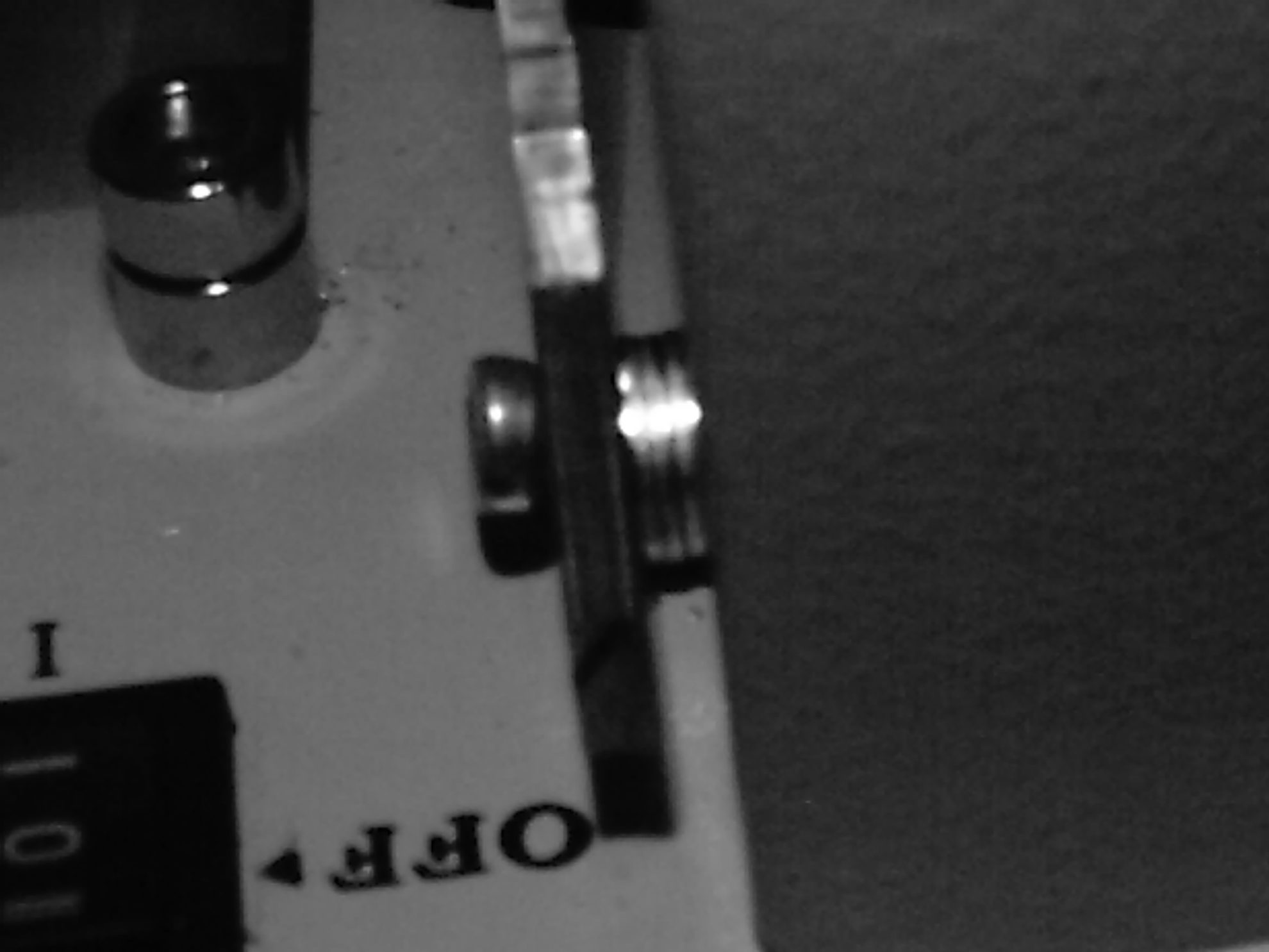
If the bottom screw isn't perfectly aligned, you'll have to insert another screw to slightly bend the caliper. (This happened to me. I used the opportunity to align the vertical position).
Of course, in this mounting, you must remove the metal strip used to measure depth. When you dismount the caliper, just pull it out and it will break. You won't need that part.
Attaching the Digital Reader
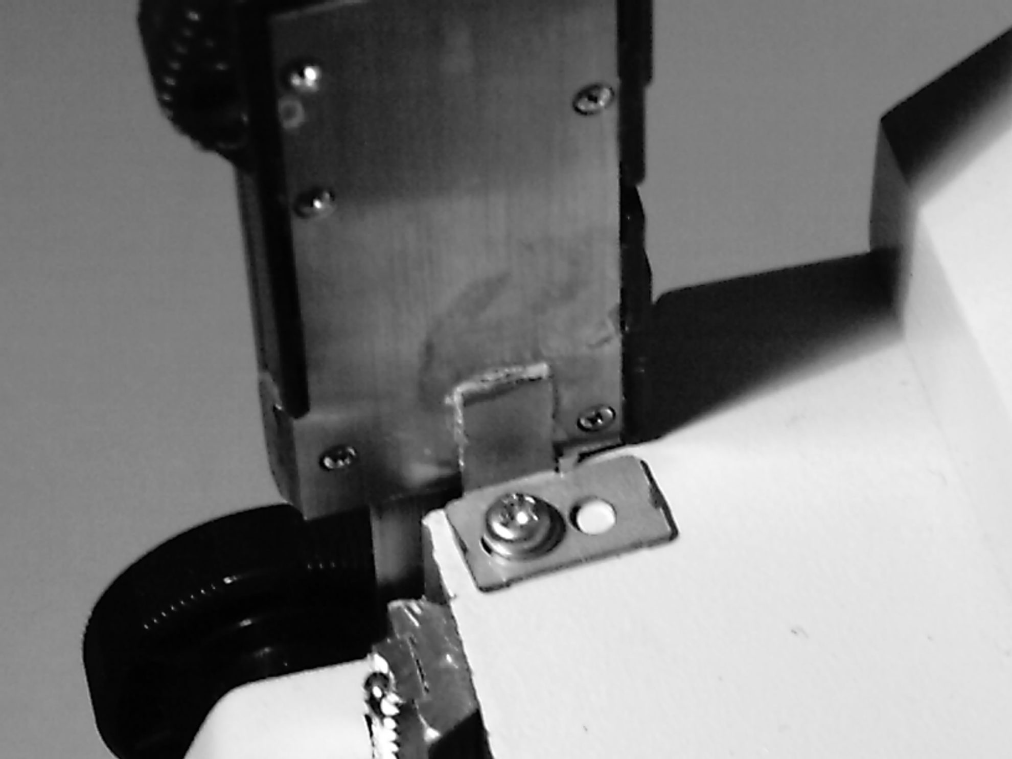
Now, you'll attach the digital reader to the upper platform of the microscope. We used an L-shaped piece of metal that we secured by drilling a threaded insertion for a small screw.
However, before doing this, you must attach the L-shaped piece of metal to the digital reader. To do this, use a glue such as Pattex Nural 21 for the cold welding between the two. After 24 hours, mark the exact position, then drill and thread the hole for the screw. (See Figure 7). If the metals don't stick well with Nural, try something like Pattex Extreme glue. Don't just do some inner gluing. Carefully build a "cover" that embraces the L-shaped piece.
If you like, you can paint the rear part of the digital reader so your device looks better. Before you do this, cover all the microscope parts completely with a painting adhesive roll. Next, cover the reader and other parts you don't want painted. A matte black color will give a professional look to the upgrade. Don't forget to protect the metal slide rule. You just want to paint the back of the reader.
If your microscope is binocular, always use only one ocular, preferably the fixed one (normally, the right one). Don't use the one that allows you to regulate the diopter (usually the left one). If you focus by looking through both oculars, mistakes can occur.
A Test Reading for an OTL RI Gemstone
Now, let's test our adaptation. I have an old stone in bad shape a friend purchased in Brazil several years ago. He said it was a cubic zirconia (CZ). By using only our upgraded microscope, let's confirm if it's a CZ or not.
Focusing
We must examine the gem with the table in a horizontal position. This position can be difficult to arrange and requires a patient approach. (I chose to mount a darkfield plate and close the iris at the point where the gem rests in a very good position).
Next, I selected a moderate magnification, such as 20X. Errors can occur above this level, due to the increased difficulty of focusing perfectly. I carefully focused the gem's table. To do this, you'll need a point on the gem on which to focus. For example, you could use dust on the gem's surface or any marks the gem may have. You could even make a small ink mark with a fine-point, non-permanent marker on the gem and use that.
Next, I pinpointed the culet too. When I thought the table was perfectly focused, I zeroed the caliper. Then, I focused the microscope to the culet. In most cases, the pinpoint mark proves very useful. When I determined it was perfectly focused, I stopped and read the caliper: 2.15 mm (0.085 inches). This marks the apparent depth of the stone.
Calculating an OTL RI
Using a gem digital caliper (Leveridge type), I know that the real depth of the gem is 3.90 mm (0.154 inch). So, by dividing the real depth by the apparent depth, we get the RI of the gem: 3.90 mm/2.15 mm = 1.814.
Consulting RI Tables
After consulting a table of gemstone RIs, I found that CZ has an OTL RI of 2.15. So, my stone wasn't a CZ after all. I searched other references until I could confirm what I already knew when I first looked through the microscope: the stone was glass. However, it wasn't any ordinary glass. It was an extra-dense flint glass. (To be sure, I also measured its specific gravity and took a spectroscopic view).
Estimating Inclusion Depth
You can also use your upgraded microscope to estimate how deep an inclusion is. Position the gem so that the inclusion you wish to measure is visible, then take a depth reading. Multiply that apparent depth by the gemstone RI. The result reveals the real depth from the surface you chose to the inclusion.
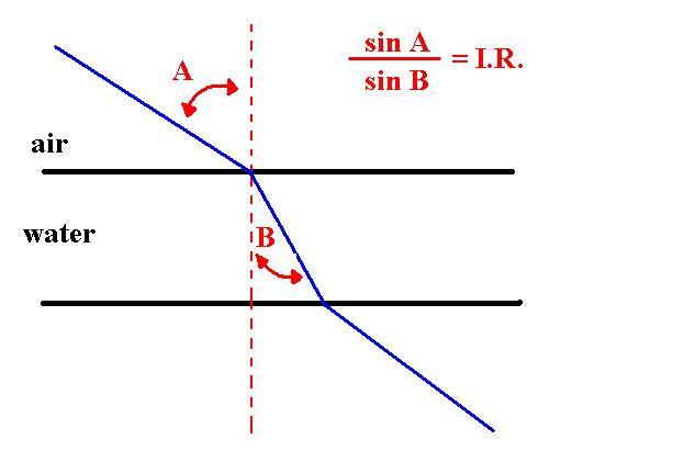
Snell's Law
The Law of Refraction, also known as Snell's Law and, in France, Descartes's Law, makes these calculations possible. Figure 8 illustrates that the sine of angle A divided by the sine of angle B equals the index of refraction.
Historical Note
The Portuguese mathematician Pedro Nunes (1502-1578) invented the device now known as the vernier. In fact, Pierre Vernier (1580-1637) applied Nunes's concepts to a linear metrical device. Many years earlier, during the Portuguese era of exploration, Nunes had described the mathematical foundations of this device and applied it to measuring angles within minutes of error. However, the name for this device, "vernier," was adopted all over the world, except in Portugal and Brazil. In these countries, the device is called a nónio, after Nunes.


Never Stop Learning
When you join the IGS community, you get trusted diamond & gemstone information when you need it.